|
Services
|
 Open
pit mining has increased substantially throughout
the western United States over the past 20 years.
During active mining, groundwater seepage, rainfall,
and surface runoff are continuously removed from the
pit. When mining and dewatering stop, water from these
sources may accumulate in the inactive pit resulting
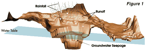
in a "pit lake". This process is illustrated in Figure
1. If the pit wall rock or bottom sediment contains
oxidizable minerals, particularly sulfide minerals,
the pit lake may turn acidic and contain elevated
concentrations of metals and sulfate. The pit lake
may then pose an environmental hazard to wildlife
and adversely affect groundwater quality. Whether
or not a pit lake develops unacceptable water quality
depends on the nature of the wall rock, the hydrodynamics
of the lake, and its hydrogeologic setting. Sulfide
oxidation is the primary process responsible for acidification
and other water-quality problems in pit lakes. Understanding
the physical and chemical processes controlling the
oxygen budget of the lake is the key to predicting
and controlling future water quality in the lake.
A typical oxygen budget for a pit lake is shown in
Figure 2. The three primary oxygen sources to the
lake are: Open
pit mining has increased substantially throughout
the western United States over the past 20 years.
During active mining, groundwater seepage, rainfall,
and surface runoff are continuously removed from the
pit. When mining and dewatering stop, water from these
sources may accumulate in the inactive pit resulting
in a "pit lake". This process is illustrated in Figure
1. If the pit wall rock or bottom sediment contains
oxidizable minerals, particularly sulfide minerals,
the pit lake may turn acidic and contain elevated
concentrations of metals and sulfate. The pit lake
may then pose an environmental hazard to wildlife
and adversely affect groundwater quality. Whether
or not a pit lake develops unacceptable water quality
depends on the nature of the wall rock, the hydrodynamics
of the lake, and its hydrogeologic setting. Sulfide
oxidation is the primary process responsible for acidification
and other water-quality problems in pit lakes. Understanding
the physical and chemical processes controlling the
oxygen budget of the lake is the key to predicting
and controlling future water quality in the lake.
A typical oxygen budget for a pit lake is shown in
Figure 2. The three primary oxygen sources to the
lake are:
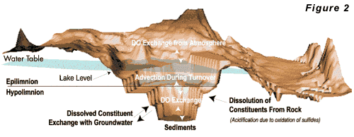 For
most pit lakes, re-aeration will be the primary source
of oxygen, although the other two sources may be important
under special circumstances. The availability of dissolved
oxygen in contact with oxidizable minerals is required
for acidification to occur. Because these minerals are
generally located in the wall rocks and bottom sediment,
whereas oxygen enters the lake from primarily the surface,
acidification is strongly controlled by hydrodynamic
mixing in the lake. Water circulation within a deep
pit lake is largely controlled by the vertical profile
of water density. Stable stratification results when
the densest water is at the bottom of the lake. Unstable
conditions occur when dense water occurs above less
dense water. The lake water density depends on water
temperature and dissolved solids content. In most pit
lakes, water temperature controls the density of the
water. Water temperature depends on climate, radiative
heating, and the temperature of groundwater seeping
into the lake. Climate is usually the most important
control on the thermal regime of the lake. A typical
heat budget for a pit lake is given in Figure 3.
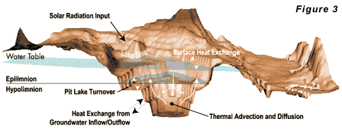 Lakes
in areas with small annual temperature fluctuations
will develop little temperature stratification. Oxygen
and chemical transport in these lakes are largely controlled
by wind-induced eddy currents, groundwater circulation,
and molecular diffusion resulting in oxygen mass transfer
to the lake bottom throughout the year. Thus, the entire
wall rock, bottom sediment, organic matter, and any
other life forms will have access to dissolved oxygen
year round. The presence of oxygen-consuming reactions
with minerals and organic matter at the lake bottom
will produce an oxygen distribution which monotonically
decreases with depth throughout the year.
 Deep lakes in colder climates develop strong thermal stratification, and transport of oxygen to deeper portions of the lake is dominated by the seasonal stability of the stratification. When the thermal stratification is stable, relatively little oxygen transport occurs between the epilimnion and hypolimnion (see Figure 2). When the stratification becomes unstable (density of the epilimnion is greater than that of the hypolimnion), the lake may turn over carrying oxygenated, shallow water to the bottom and deep, mineralized water to the surface. In climates where the surface water temperature remains above 4o C (39o F), a lake may turn over once a year in the winter. In colder climates, where the surface water cools below 4o C, lakes may turn over in both the fall and spring. Most of the larger existing pit lakes contain water that does not meet drinking water standards, agricultural water quality standards, or aquatic life standards. Given the recent mining activity in the West, numerous pit lakes may be expected to form over the next 20 to 50 years. Because most pit lakes have yet to form, mathematical models represent the only way to estimate their ultimate environmental impact. The ability to predict the hydraulic structure of pit lakes may lead to development of operation strategies for controlling their chemistry. Hydro Geo Chem has initiated a research program to better understand the water quality and dynamics of this new type of human-made water body. Results of this research will be used to assess and mitigate the potential environmental effects of pit lakes. Reference: Thomann, R.V. and J.A. Mueller. 1987. Principles of surface water quality modeling and control. Harper Collins, New York, NY.Efficiency of Air Sparging Trenches
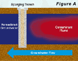
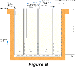
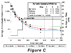
Two approaches to air-sparging are common. The first involves injecting air through wells into the contaminated portion of the aquifer, thus directly attacking the contaminant plume. The second approach creates a barrier to VOC transport by sparging downstream from the contaminated zone (see Pankow and others, 1993). In the sparging barrier approach, a sparging zone is created using vertical wells, horizontal wells, or trenches to inject air at a location where the contaminated groundwater will move through the sparging zone (Figure A). To the extent that the design is successful, VOCs are removed from the groundwater as it passes through the sparging zone and the water is aerated to enhance biodegradation of less volatile compounds. Hydro Geo Chem, Inc. recently completed a detailed pilot study of the performance of a trench sparging system at a site in Arizona that was contaminated with gasoline-range petroleum hydrocarbons. The test was designed, in part, to determine the efficiency of the sparging trench in removing benzene, toluene, ethylbenzene, and total xylenes (BTEX) at various air injection rates. The results of the test are summarized in Figure C which shows the concentrations of the target compounds measured in the trench with time, as the air injection rate was increased. The continuous lines in Figure C represent the concentrations of each compound predicted by a mathematical model of the sparging process. The model accounts for the dimensions of the sparging trench, the air injection rate, the groundwater flow rate, the gas-water partitioning coefficient (Henry’s Law coefficient) of the compounds, and the dynamic sparging efficiency. The dynamic sparging efficiency represents the effect of deviations from complete chemical equilibrium between the contaminated water and the sparge air on the sparging rate. The model is used to calculate the dynamic sparging efficiency at each air injection rate by adjusting the efficiency factor to match the observed concentrations. Reference: Pankow, J.F., R.L. Johnson, and J.A. Cherry. 1993. Air sparging in gate well in cutoff walls and trenches for control of plumes of volatile organic compounds (VOCs). Ground Water. vol. 31, no.4, pp. 654-663.Gary
R. Walter, Ph.D., R.G.
Jinshan Tang, M.S.
The Resource Conservation and Recovery
Act (RCRA) will be getting a long-awaited facelift.
The corrective action process has been behind current
management practices and out of sync with other EPA
programs for about 10 years now. The EPA has finally
published an Advance Notice of Proposed Rule Making
(ANPRM) in the May 1, 1997 Federal Register which would
restructure RCRA’s Subpart S. The objectives of the
proposed revisions are to make remediation standards
more consistent with other EPA programs, streamline
the process to achieve faster closure instead of focusing
on regulatory reviews and paperwork, make remedial goals
more practicable and realistic, and reduce costs.
The Notice for Proposed Rule Making (as opposed to the advance notice) for the Subpart S revisions was originally scheduled for mid-1997, but has been delayed until December 1997. At that time, only some of the revisions will be officially proposed, while others will be re-crafted. The final rulemaking is anticipated in December 1998. So, these rules aren’t a quick fix, but the start of a long process that should result in more efficient and cost-effective RCRA corrective actions. Alternate Regulatory Acronyms: Doyne Wrealli, B.A.
Every year, BTI Consulting Group, Inc.
interviews organizations that use environmental services
about individuals and organizations that are most effective.
This year, BTI conducted 630 open-ended, unprompted
interviews of these customers, who, altogether, nominated
104 service providers in the US.
HYDRO GEO CHEM, INC.
|


