Winter
1998
In
This Issue:
Chemical
Incompatibility of Bentonite with DNAPLs
Acid
Rock Drainage: Challenge for Mining
Limitations
of Hydraulic Containment for Plume Management
Chemical
Incompatibility of Bentonite with DNAPLs
Bentonite clay has many environmental
applications where a hydraulic barrier is desired.
For example, bentonite can be used to construct
slurry walls, annular seals in wells, liners, covers
and to backfill exploratory borings. Bentonite-based
barriers are sometimes constructed at hazardous
waste sites to separate dense non-aqueous phase
liquids (DNAPLs) from the surrounding groundwater.
A recent laboratory investigation identified structural
incompatibility between bentonite seals and DNAPLs
(McCaulou and Huling, 1998). Bentonite seals constructed
in double-ring permeameters deteriorated and hydraulically
failed when exposed to trichloroethylene (TCE),
methylene chloride (MC), and creosote. These results
indicate that current guidelines for constructing
wells (U.S.E.P.A. RCRA, 1992) and slurry wall systems
at hazardous waste sites may be inadequate with
regard to DNAPLs.
The
following summary highlights the observed effects
of DNAPLs on bentonite seals under different exposure
scenarios.
 Permeability to Saturated
Aqueous Concentrations of TCE, MC, and Creosote
Permeability to Saturated
Aqueous Concentrations of TCE, MC, and Creosote
Hydration and exposure of bentonite
with water containing saturated concentrations of
TCE, MC, and creosote did not alter its hydraulic
conductivity relative to water. These results indicate
that bentonite structures in heavily-contaminated
groundwater, but outside the DNAPL zone, may resist
chemical desiccation and hydraulic failure. However,
bentonite barriers containing soluble concentrations
of these compounds may be a long-term source of
dissolved organic compounds to the surrounding groundwater
after the designed remediation period.
DNAPL
Immersed Bentonite Pellets and Subsequent Water
Hydration / Permeation
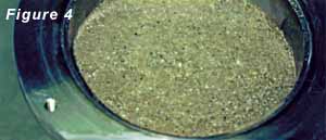
Bentonite pellets immersed in DNAPL
retained their rigid shape, did not swell, and did
not form a hydraulic barrier. However, when the
DNAPL was removed and replaced with water, the DNAPL-wetted
pellets imbibed water to swell and form a competent
hydraulic barrier (Figure 4). However, discrete
zones of DNAPL remained in the bentonite. These
results indicate that bentonite pellets exposed
to DNAPL retain their swelling potential and will
retain some of the DNAPL as a source of organic
compounds after hydration.
 Water Hydrated Bentonite Permeated with DNAPL
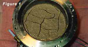
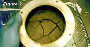
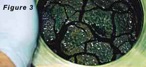
Competent hydraulic barriers constructed
with bentonite pellets, hydrated with water, and
exposed to liquid TCE, MC, and creosote deteriorated
(Figures 1, 2, and 3). Deterioration involved the
formation of desiccation cracks up to 5 mm wide.
Cracks were largest at the top of the barrier and
were not preferentially located at the sidewall
interface. Vertical cracks initiated at the surface
intersected with other near horizontal cracks that
appeared to connect to other vertical cracks below.
The intrinsic permeability of water-hydrated bentonite
permeated with DNAPL was 46 to 2,640 times greater
relative to water. The network of cracks facilitated
the rapid, preferential flow of DNAPL through the
clay.
TCE
Permeability of Bentonite Grout and Sand Mixtures
to TCE
Silica sand is expansively inert,
yet, 50%, 75%, 83%, 90%, and 95% (wt silica sand/wt
bentonite) mixtures with bentonite grout were insufficient
to prevent desiccation cracking and/or hydraulic
failure. Results indicate that the addition of sand
to bentonite decreases the resistance to water flow
and the bentonite remains vulnerable to chemical
incompatibility mechanisms.
 Effect of Hydraulic Head on Permeability
Visible cracks formed in bentonite
exposed to TCE in less than 1 week at 25 feet of
total head, approximately 1 month at 5 feet of total
head, and in 3 months under hydrostatic conditions
(1 inch TCE) indicating that the rate of desiccation
crack propagation was positively correlated with
pressure. However, formation of desiccation cracks
under hydrostatic conditions indicates that the
processes that initiate chemical desiccation are
dependent on chemical reactions and not solely dependent
on hydraulic pressure.
Additives
Which May Decrease Incompatible Effects Between
DNAPLs and Bentonite
Presently, additives to bentonite
are under evaluation to minimize the effects of
incompatibility. Additives being tested include
organophilic clays, gelling agents, and surfactants.
Test results and data interpretation have not been
completed.
 Conclusions
These laboratory investigations point
to the possibility that DNAPL may compromise the
integrity of various types of bentonite barriers.
The incompatibility between bentonite and these
DNAPLs indicate that the structural integrity of
hydraulic barriers may be compromised at the critical
locations they were designed to hydraulically isolate.
The
laboratory conditions under which these investigations
were performed do not, however, replicate field
conditions. Caution should, therefore, be used in
extrapolating these results to field conditions.
References:
McCaulou,
D. R., and S. G. Huling, 1998, Compatibility of
Bentonite and DNAPLs, Groundwater
Monitoring and Remediation, (to be submitted, January
1998)
U.S.E.P.A.
RCRA Groundwater Monitoring Technical Guidance Document.
1992.
Washington D.C. EPA/530-R-93-001.
-
Return to Top Of Document -
The technological challenge of preventing
and controlling acid rock drainage (ARD) was the
central topic of the Fourth Annual International
Conference on Acid Rock Drainage (ICARD) in Vancouver,
B.C.
Although
ARD can occur naturally where sulfide minerals are
exposed to weathering, the conference focused on
prevention and mitigation of acidification and metal
contamination that can result when ground or surface
water contacts metal sulfide-bearing rock exposed
by mining. The conference emphasized hard rock metal
mining, but the information reported was applicable
to coal mining, quarrying, and industrial processing;
the fundamental physical and chemical processes
controlling the environmental fate and transport
of acidity and metals are the same.
The
conference proceedings were organized into five
sections: special presentations by ICARD sponsors,
prediction, prevention, treatment and control, and
monitoring and restoration. Several ICARD sponsors
provided examples of how their companies proactively
use geochemical methods of ARD prediction to classify
waste rock and develop waste-management strategies
for ARD prevention in planning new mining operations.
Papers
were presented on a wide range of topics: geochemical
and mineralogical characterization methods for predicting
future chemical loading from rock, tailings, and
sludge; evaluations of cover designs to reduce or
eliminate moisture and oxygen transport; subaqueous
disposal methods; the limnology and geochemistry
of pit lakes; and treatment of solids and liquids
using chemical and biological methods, to name just
a few.
The
diversity of topics in the proceedings exemplifies
the great variety of options and issues facing the
mining industry worldwide. Although significant
progress has been made in the prediction and control
of ARD over the last ten years, no standard approach
exists to evaluate the potential for or the mitigation
of ARD. Only by careful analysis of site-specific
physical, chemical, and operational conditions can
comprehensive options be developed to cost-effectively
prevent or control ARD.
-
Return to Top Of Document -
 So-called "pump and treat" is a generally
accepted approach for controlling the migration
of contaminants in groundwater. The approach is
based on the concept, illustrated in Figure A, that
a pumping well creates a capture zone in which all
groundwater eventually flows to the well. The edge
of the capture zone is defined by a bounding streamline.
The bounding streamline is a hydraulic barrier in
the sense that no macroscopic flow of water occurs
across the bounding streamline under steady flow
conditions (Bear, 1979). Thus, in theory, the well
establishes a hydraulic capture zone around the
area of contaminated soil or groundwater and prevents
dissolved contaminants from leaving the capture
zone. In practice, hydraulic containment may not
prevent plume migration for several reasons: failing
to consider the effects of hydrodynamic dispersion;
failing to consider the effects of short-term variations
in natural groundwater flow velocities; and failing
to consider the effects of variations in groundwater
pumping rates.
So-called "pump and treat" is a generally
accepted approach for controlling the migration
of contaminants in groundwater. The approach is
based on the concept, illustrated in Figure A, that
a pumping well creates a capture zone in which all
groundwater eventually flows to the well. The edge
of the capture zone is defined by a bounding streamline.
The bounding streamline is a hydraulic barrier in
the sense that no macroscopic flow of water occurs
across the bounding streamline under steady flow
conditions (Bear, 1979). Thus, in theory, the well
establishes a hydraulic capture zone around the
area of contaminated soil or groundwater and prevents
dissolved contaminants from leaving the capture
zone. In practice, hydraulic containment may not
prevent plume migration for several reasons: failing
to consider the effects of hydrodynamic dispersion;
failing to consider the effects of short-term variations
in natural groundwater flow velocities; and failing
to consider the effects of variations in groundwater
pumping rates.
 Hydrodynamic
Dispersion
Hydrodynamic
Dispersion
In the simplest case, the movement
of contaminants in groundwater is controlled by
two processes: advection, which is the movement
of dissolved contaminants with and in the same direction
as the bulk groundwater flow; and hydrodynamic dispersion,
which is the spreading of dissolved contaminants
due to both small-scale variations in flow directions
and molecular diffusion. Hydrodynamic dispersion
results in the spreading of contaminants from zones
of higher to lower concentration and transverse
to the direction of bulk groundwater flow.
This
process is illustrated in Figure B which shows the
large-scale position of the bounding streamline
zone and the small-scale pathways that water and
contaminants actually follow. Even though the average
direction of flow is toward the well, the actual
paths of water flow back and forth across the bounding
streamline. If the water flowing inside the capture
zone near the bounding streamline is contaminated,
the contaminants will cross the bounding streamline
and be outside the capture zone. Due to the simultaneous
action of molecular diffusion, which results in
an irreversible movement of contaminants from zones
of higher to lower concentrations, not all of the
contaminant mass that leaves the capture zone at
one location will return. This process can result
in a “bleed” of contaminants out the capture zone,
as illustrated in Figure C.
 Many pump-and-treat systems work because the wells
are pumped at a high enough rate that the capture
zone encompasses not only the contaminated portion
of the aquifer, but also uncontaminated groundwater.
In such cases, the groundwater flowing near the
edge of the capture zone is either uncontaminated
or contains very low concentrations of contaminants.
Contaminant bleed out of the capture zone is thus
limited by a buffer zone of relatively clean water.
Even in this best case, however, the principles
of mass transport discussed dictate that some contaminant
mass, albeit small, will eventually disperse out
of the capture zone.
Many pump-and-treat systems work because the wells
are pumped at a high enough rate that the capture
zone encompasses not only the contaminated portion
of the aquifer, but also uncontaminated groundwater.
In such cases, the groundwater flowing near the
edge of the capture zone is either uncontaminated
or contains very low concentrations of contaminants.
Contaminant bleed out of the capture zone is thus
limited by a buffer zone of relatively clean water.
Even in this best case, however, the principles
of mass transport discussed dictate that some contaminant
mass, albeit small, will eventually disperse out
of the capture zone.
Problems
with contaminant bleed may become significant, however,
when the capture zone is established so as to just
barely encompass the contaminated portion of the
aquifer. In this case, contaminated water will be
flowing near the boundaries of the capture zone
and significant bleed may occur due to hydrodynamic
dispersion.
Variations
in Groundwater Flow and Pumping
The location of the bounding streamline
of the capture zone is determined by the ratio of
groundwater pumping to the background rate of groundwater
flow. At a particular site, the background rate
of flow may be affected by short-term variations
in recharge, seasonal variations in groundwater
levels, and pumping by third parties. At sites near
rivers, the rate and even direction of groundwater
flow may vary significantly depending on river stage.
These uncontrolled factors will cause the position
of the bounding streamline to change with time unless
appropriate adjustments are made to the pumping.
An analysis of the influence of these factors will
be presented in an upcoming issue of the Gradient.
References:
Bear, J. 1979. Hydraulics
of Groundwater. McGraw-Hill, NY.
-
Return to Top Of Document -